
? ? ? AGV is the abbreviation of “Automated Guided Vehicle”, which means “automatic guided transport vehicle”. It is equipped with automatic guiding device such as electromagnetic or optical. It can travel along the prescribed guiding path, with safety protection and various shifts. Functional transport vehicle。
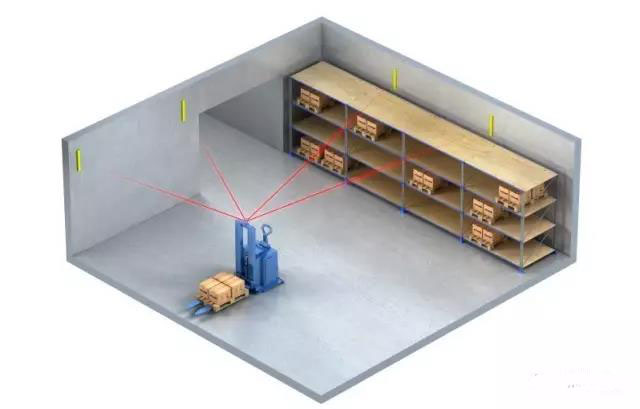
Figure 1 Schematic diagram of AGV laser navigation
In the early development of AGV, AGV mainly focused on electromagnetic navigation and tape navigation. This AGV navigation is stable, reliable, economical and practical, but it also has the following drawbacks:
1. Electromagnetic navigation requires construction of the ground slot and backfilling to destroy the original ground integrity.
2, tape navigation needs to be pasted on the ground, and later it is easily damaged by other vehicles and personnel.
3. The post-process requirements for modifying the AGV line require re-construction (increased cost).
4. The overall beauty of the workshop is not perfect.
In this historical context, based on the electromagnetic navigation and tape navigation of AGV, another new AGV navigation method is urgently needed to solve the drawbacks of the scalability of electromagnetic/tape navigation.
?
Q1: How to develop AGV positioning navigation sensor?
People first think of whether there is a GPS-like positioning system that can be used indoors and with positioning accuracy in the millimeter range. In the 1970s and 1980s, with the continuous development of laser technology, the laser ranging accuracy was gradually improved. People began to try to use laser as the measurement positioning, and under the continuous experimental efforts, successfully developed a two-dimensional laser scanner.
|
Laser safety class classification (IEC standard) Class 1 The Class 1 grade is a low-energy laser that is very safe and avoids all static hazards and no biological damage. The laser does not cause damage to the human body or skin under any conditions. Therefore, Class 1 laser sensors do not require additional safety measures other than laser grade labels. |
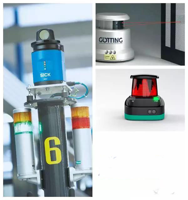
Figure 2 2D laser scanner
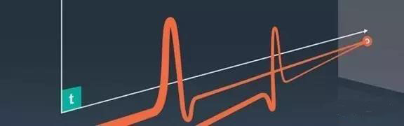
? ? The 2D laser scanner is an instrument that uses the time flight principle to measure the size and shape of the target. The 2D laser scanner measurement system is based on the principle of laser ranging. The two-dimensional scanning surface is formed by the rotating optical component to realize the area scanning and contour measuring functions. Two-dimensional laser scanner products are widely used in anti-collision, measurement, navigation, security, etc., such as AGV navigation, equipment collision avoidance, vehicle detection, sensitive area protection.
? ?
Figure 3 AGV laser scanner working principle diagram
Laser scanner
The laser navigation of the reflector is to continuously emit laser pulses through the laser emitter, and the laser pulse is emitted by the rotation mechanism at an angular interval (angle resolution) to all directions within the scanning angle to form a radial coordinate reference. Dimensional scanning surface. The laser radar recognizes the position information (X, Y) of the laser reflector by recognizing the surface reflectance of the object within the scanning range, and calculates the position and attitude information of the AGV where the laser radar is located by the position of at least three reflectors (X ,Y,a)
? ?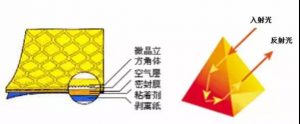
The inside of the reflector is a triangular prism structure that can achieve the same path reflection of incident light. The reflectivity of the reflector is much larger than the surface of an ordinary object. Therefore, the laser can recognize the reflector from the target by the difference in surface reflectance.
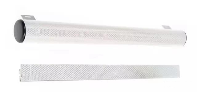
Figure 4 Reflector (plane, cylinder)
|
Flat? reflector |
Cylindrical? reflector |
|
| N° of reflectors | More | Less |
| Use specular reflecting ?surfaces, like windows or steel plates, behind reflectors | Possible | Never* |
| Optimal for use in outer ?corner | No | Yes |
| Important edges for reflector ?bearing calculation | Right |
Right &Left |
| Mounting | “Easy” | “Hard” |
* A more reflective surface behind a cylindrical reflector may cause the AGV navigation sensor to detect a false reflector. As shown below.
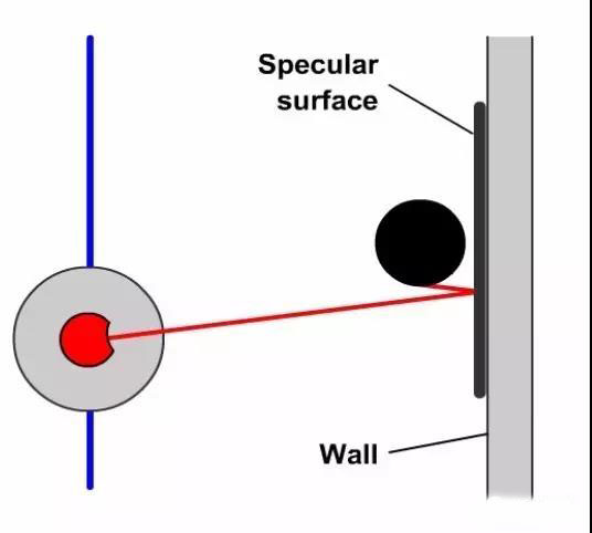
Figure 5 Schematic diagram of the abnormality caused by the reflective wall
?
1. Measure the coordinates of the reflector
Measure the position of the reflector
If the AGV wants to use the reflector as a reference for its navigation, it must first obtain the coordinates of the on-site reflector. At present, the two-dimensional laser navigation scanners on the market now have the function of measuring the position coordinates of the reflectors deployed on the field workshop. AGV professionals only need to measure the AGV vehicle at the specified location, and use the 360-degree rotary scanning function of the 2D laser scanner to obtain the position information of all the reflectors in the current environment.
The position information of the obtained reflector is adjusted, rotated, and edited by a specific software, so that the information of the reflector is consistent with the layout of the workshop.
The processed reflector coordinate information is compiled and downloaded to the AGV controller (some brands need to be downloaded into the 2D laser navigation sensor).
?
?
2. Positioning and navigation
Positioning and navigation
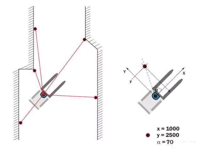
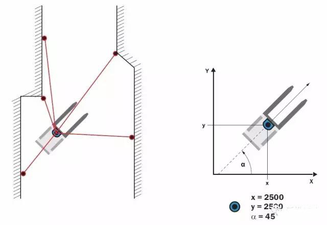
After the AGV measures the position data of the on-site reflector, the laser scanner obtains the distance between the scanner and each reflector through the rotation measurement, and at least three reflector distance values, and calculates the current coordinate position of the laser scanner by the triangulation method. .
The positioning algorithm of AGV navigation–triangulation method.
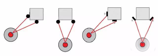
1. Reflector installation recommended
| Recommended method: Use the reflector as shown above in the range of 90 degrees. AGV can achieve maximum positioning. |
| Not recommended: The installation method above, this method fails to achieve optimal coverage of the reflector over a wide range of 90 degrees. |
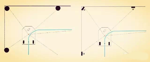
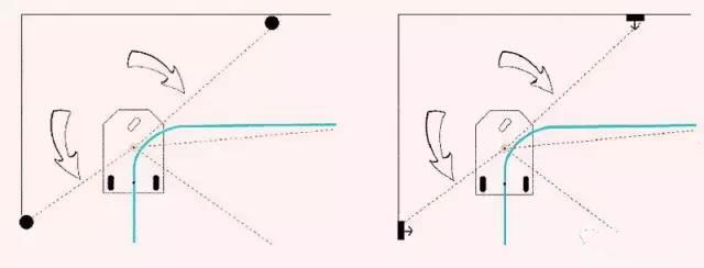
2. Double reflector situation
Double reflectors are reflectors that are similar in angle to each other as seen from the perspective of the laser scanner. They cannot be accurately distinguished by the system. This situation is called “double reflector”.
The laser scanner performs a measurement algorithm evaluation function on the reflector. As long as the longitudinal depth of the double reflector is maintained at least 4 meters, the laser scanner can distinguish the double reflector from the double reflector within a certain angle. In this case, the mirror detected in the first counterclockwise direction is a true reflector, and the second may be considered as the shadow of the first detected reflector in the reflector.
According to the above technical principle, the AGV travel route is parallel to the wall (the reflector has been deployed on the wall) or a row of columns (the deployment of the illuminating panel), and the laser scanner can distinguish the reflector in a certain overlapping angle. Of course, the premise of distinguishing is that the distance between the double reflectors is greater than 4 meters.
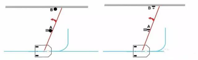
Figure 6 At the current position, the A reflector is better than the B reflector.
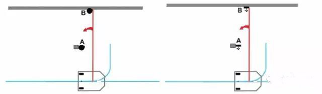
Figure 7 At the current position, the B reflector is better than the A reflector.
3. Reflector detection distance
In AGV applications, the laser scanner measures the range of distances and is able to detect a sufficient number of real reflectors, minimizing the effects of false reflectors. The false reflector is a hassle for laser navigation, so it is important to have enough reflectors within the limited measurement distance of the laser scanner.
The following setting laser scanner effective measurement distance is 25 meters
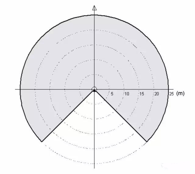
Figure 8 The area where the cylindrical reflector is detected (270 degrees is detected)
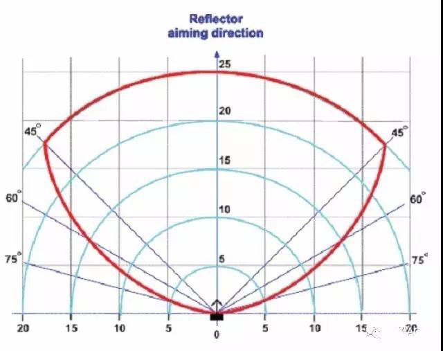
Figure 9 The area where the planar reflector is detected (detection distance is 25 meters)
As can be seen from the above figure, the planar reflector can detect 25 meters at a maximum of 45 degrees. At 60 degrees, the farthest detection reflector is 15 meters. At 75 degrees, the detection distance is 5 meters.
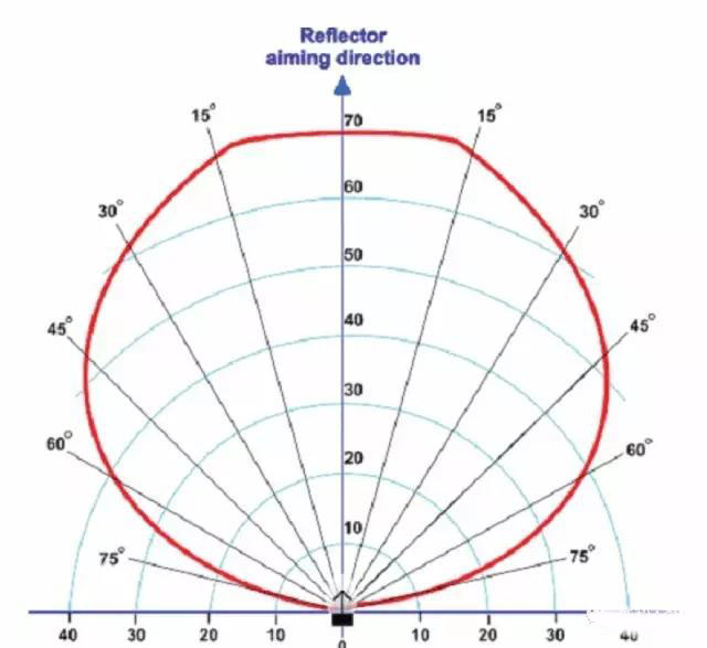
Figure 10 The area where the flat reflector is detected (detection distance is 70 meters)
Some brands of laser scanners have a detection distance of 70 meters and a laser scanner with a detection distance of 70 meters. They are mainly used in outdoor applications. The longer the detection distance is, the stronger the sensitivity of the laser scanner is. Reflectors are more sensitive. The white wall reflection rate of 1 meter is equivalent to the reflection rate of the reflector 70 meters away. Therefore, the farther the laser scanner is set, the more important it is to require a more rigorous reflectorless environment.
?
1. Pillar installation reflector principle
The principle of installing two reflectors on one column: the laser scanner cannot simultaneously detect two reflectors on the same column at any position. In order to ensure that the two reflectors cannot be detected at the same time, the most effective way is to have the two reflectors mounted away from each other.
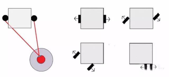
Recommended installation method (reflector back to back installation)
Installation method is not recommended (2 reflectors are detected at the same time)
2. Cylindrical reflector and wall
Cylindrical reflectors typically require a smaller number of deployments than planar reflectors. In both cases, the most important thing is how to solve the asymmetry deployment of the reflector.
When the AGV walking long distance line is parallel to the wall where the reflector is deployed (the lines formed by the multiple reflectors are parallel to the wall), and close. The minimum distance between the route requiring the AGV to travel and the wall must be greater than 0.7 meters.
Use the following formula, remember not to exceed the maximum: DR ≤ 10 * DW, DW ≤ 20 meters
among them:
DW: The laser scanner is located at a distance of 0.7 m from the wall (reflector).
DR: The distance between the reflectors.
We recommend the maximum deployment as:
?
DR≤10*DW且DR≤20米
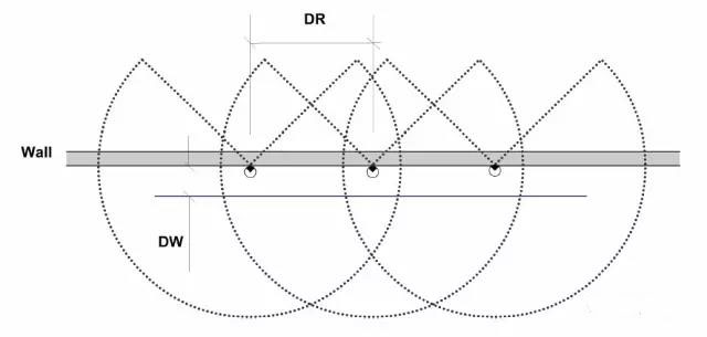
Figure 11 cylindrical reflector deployment plan
3. Plane reflector and wall
The advantage of the 45o installation is that the reflector is visible in one direction.
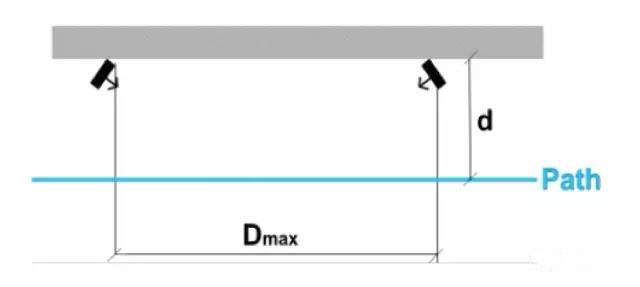
Figure 12 45 degree reflector installation and deployment plan 1
Under normal wall conditions, the risk of false reflectors is low, and the spacing Dmax between the reflectors is up to 5 to 6 times the distance d of the nearest path. In this spatial range, the scanner cannot scan any reflectors in a short period of time and then does not adversely affect the navigation along the wall.
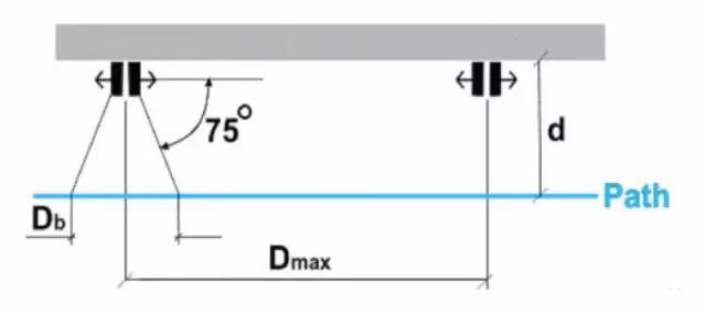
Figure 13 Back-to-back reflector installation and deployment plan 2
This solution has the same characteristics as Option 1, and the advantage of this deployment is that the scanner can be remotely detected along the AGV line. The disadvantage is that the scanner reaches the reflector position with a dead zone Db.
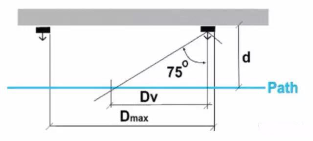
Figure 13 Wall-mounted reflector installation plan 3
The reflectors are mounted parallel to the wall and the range in which each reflector is detected is limited. Due to the characteristics of the reflector, the maximum angle of detection is about 75 degrees, and the effective detection range is:
?
Dv = d*tan(75°) = 3.7*d
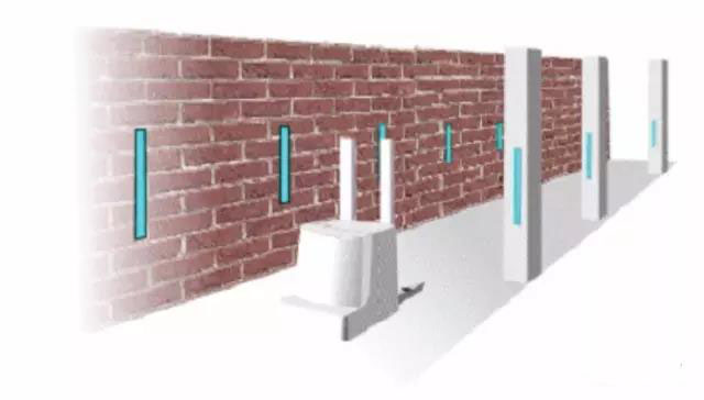
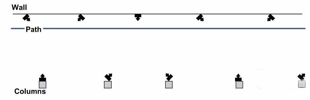
Figure 14 Example of mixed installation at different angles
The spacing between the columns is 10m, the AGV path is 2m from the wall of the wall, and the spacing between the reflectors along the wall is about 10m.
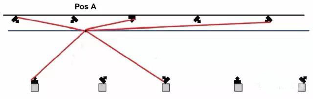
Figure 15 Position A detects the number of reflectors
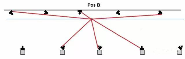
Figure 16 Position B detects the number of reflectors
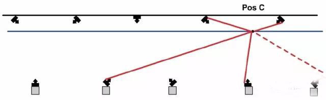
Figure 17 Position C detects the number of reflectors
4. Cylindrical reflectors and corridors
The number of cylindrical reflectors is relatively small compared to planar reflectors. But the layout is in an asymmetrical form.
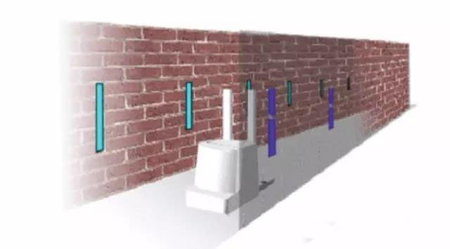
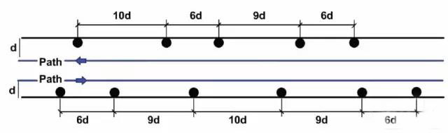
Figure 18 Example of deploying a cylindrical reflector in a corridor
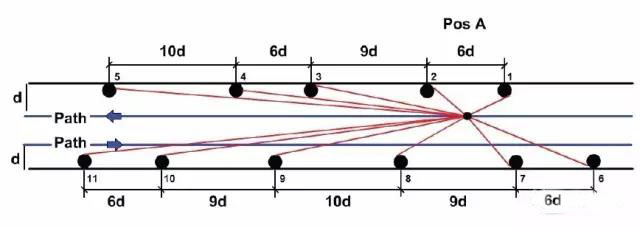
Figure 19 Position A detects the number of reflectors
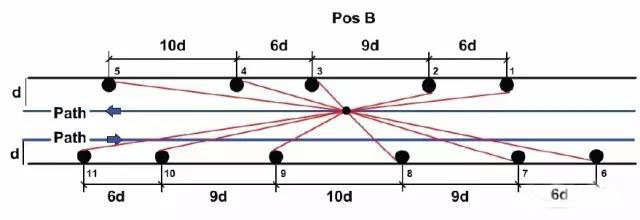
Figure 20 Location B detects the number of reflectors
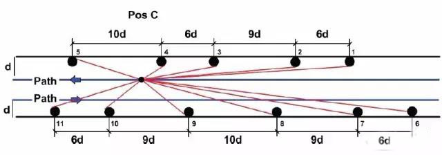
Figure 21 Location C detects the number of reflectors
5. Planar reflectors and corridors
The distance between the reflectors is 5 times the distance between the path and the wall. The distance between some reflectors is 4 or 6 times, which is intended to prevent the symmetry of the reflector.
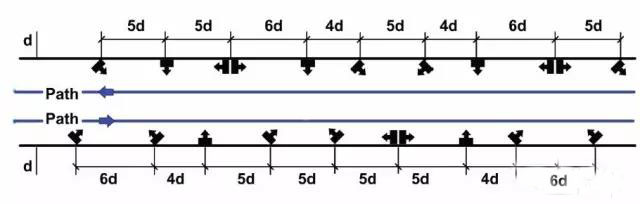
Figure 22 Example of deploying a planar reflector in a corridor
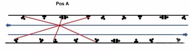
Figure 23 Location A detects the number of reflectors
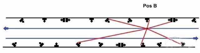
Figure 24 Position B detects the number of reflectors
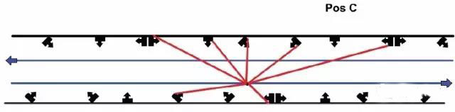
Figure 25 Location C detects the number of reflectors
6. Reflector deployment of loading and unloading station
The layout of the loading and unloading station requires high positioning accuracy of the AGV. Therefore, the reflector is designed scientifically, systematically and in a targeted manner in the layout design of the reflector.
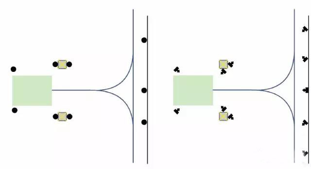
Figure 26 Reflector deployment around the station (preventing symmetry)